Wednesday, August 25, 2010

BinaryTrees For Rescue

When ArrayLists become big reverse lookups like indexOf, lastIndexOf, contains and the modifications methods can slow down your program. When order is not important, you might use a HashMap. In some other cases you have a constant key-value, that can be use in a TreeMap. If you need to have to update the index however there is no real alternative. What I'm missing in the java collections is a balanced tree, allowing me to traverse it's structure. The NavigableSet-Interface available since Java 6 only allows to traverse the elements. There are no methods to access the tree-structure. I wonder why the tree used in TreeMap wasn't made available in a separate Red-Black-Tree class.

As mentioned before trees can be very useful when search through big datasets. Imagine you have a texteditor with more than 10000 lines of text and you need a mapping from lineNumber to line and line to lineNumber. One possibility is to put all lines as keys in a map and use the index as a value, but than you have to update the map every time, you insert a new line. Using a tree, you can insert the lines at a certain position and put the treenode instead of the index into the map. Now you can lookup up the treenode for a line. Calculating the index of a treenode is not difficult:
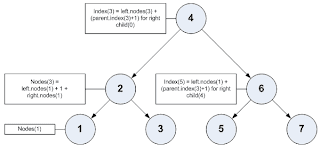


To speed up the calculation you can cache the node-count of each subtree in the corresponding rootnode and only recalculate it, when a subtree node changes. This way a lookup of a treenode by it's current index or calculating the a treenode index should be very fast enough.

The calculation of the index can be easy adapted to similar cases. For example if you have a texteditor supporting different line heights, calculating the y-Offset of a single line is expensive. Calculating the y-offset of a line requires to sum up all height of the previous lines. Having all lines in an Arraylist means to iterate through the hole list beginning from the first line. You may think about caching the line-offset in a treemap, but than you have to clear all entries after the modified line. In worst case if the first line changes, the while cache is invalid. With a tree, you can store the sum of heights in the treenodes. If the height of one line changes, you only have to recalculate the value of parent nodes. Caluating the y-Offset is now much cheaper, just sum up the height of the lines in all left-children and the height of the line stored in the node, when following a right-child. The only difference to the index calculation is that, that a treenode adds the height instead of the constant node count 1 when including it's own value.

Comparing the speed of an arraylist with the speed of the tree, isn't an easy task. There are many things to consider:

a) if the dataset is rarely modified and the dataset isn't to big, a map can be used to improve the reverse lookup
b) the speed for an indexOf/lastIndexOf/contains lookup an the arraylist strongly depends on the speed of the equals and hashcode method. For example for integers this is very fast.
c) the number of different elements, if you have only 10 different elements in the list and they are random, the results of indexOf/lastIndexOf/contains will need much less comparisons
d) a tree needs more memory
e) for looking up an element by an index there is nothing faster than an array and same applies for creating complete copies it.

I think the main reason for not including a balanced binary tree in the java collection as a separate class, is that the arraylist in most cases is fast enough. Wether to use a tree, hashmap, arraylist or linkedlist dependends on what you want to do. There is no golden hammer, that solves all your problems.

Sunday, August 8, 2010

DCI and actifsource

In my last post I introduced the modified DCI meta model. Let's have a look at a simple example.

The use case we would like to implement is to transfer money from a money source to a money sink. MoneySource and MoneySink are specific roles, played by an appropriate bank account.

The example is built up on the following entities:


UseCase: TransferMoney
From a users point of view the use case is the most important artifact in the code. That's because the use case contains business relevant code.

The following UseCase shall transfer money from a MoneySource to a MoneySink. Furthermore the amount of money shall be passed to the use case as an argument.

Role: MoneySource and MoneySink
Let's have a closer look at the roles needed. The MoneySource has an interaction balance() to ask for the current balance. Furthermore the role supports withdraw() to withdraw an amount.

Note that we specify that this role might be played by an InvestmentAccount or a SavingsAccount.

MoneySink on the other hand side supports the interaction deposit() to deposit an amount.


Note that this role might be played only by the SavingsAccount.

Data: InvestmentAccount and SavingsAccount
The InvestmentAccount shall have a Balance member to store the actual balance. Furthermore the method withdraw() supports withdrawal. Therefore it might play the MoneySource role.


The SavingsAccount supports withdrawal and deposit. Therefore it might play the MoneySink or MoneySource role.


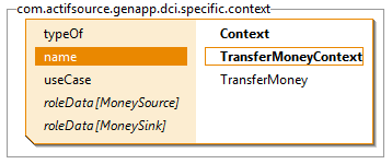
Context: TransferMoneyContext
The context now puts it all together. Every context has to specify exactly one UseCase. In the following example we choose the TransferMoney UseCase.

Since the UseCase TransferMoney declares the usage of the Roles MoneySource and MoneySink actifsource asks us to provide the data which can play the roles.

Using content assist to selected the data object for the MoneySource role we can choose between the InvestmentAccount and the SavingsAccount. As we have seen before both accounts have a withdraw member and are therefore able to play the MoneySource role. For this example lets choose the InvestmentAccount.
Last but not least we have to specify the data for the MoneySink role. Using content assist on the data field only allows the SavingsAccount. Thats because only the SavingsAccount allows to deposit an amount.

The TransferMoneyContext has been declared for the UseCase TransferMoney. Since TransferMoney stated to work with the Roles MoneySource and MoneySink we have to provide Data which can play this roles.

Thanks to the strong actifsource type system it becomes possible that the content assist allows only Data which can play the role needed.


The DCI Meta Model

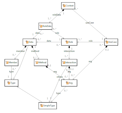
In my previous blog I promised to work out a meta model to realize the DCI architecture. As explained before I've made a slight modification: a UseCase is modeled as its own entity.

UseCase
A UseCase is business relevant code which needs different actors (data objects playing roles) to work on.

Context
The context manages the UseCase an the data objects which are able to play the roles needed.

Role
A role is an interface which can have 1..N interaction (an interaction is realized as an abstract method on the role interface).

Every role might be realized for any suitable data object. A role realization for a specific data object is called Adapter.

RoleData
Setting up a context it must be determined which data object plays the roles needed.

Data
Data objects contain members and method. Members are simple data fields an result in an appropriate getter function. The method can be freely chosen and realize a more sophisticated access to the members.


The DCI Architecture

In his new book "Lean Architecture: for Agile Software Development" James O. Coplien shows up with a new programming paradigm: The DCI Architecture.

Before reading this blog I suggest to have a look a the DCI vision document:
http://www.artima.com/articles/dci_vision.html

Let me try to explain DCI in a nutshell.

The idea of DCI is to separate data from business code for better readability while the business code is directly expressed as use case.
DCI stands for Data, Context and Interaction.

Data
Data means POD (plain old data) objects without any business relevant methods.

Context
A context is a place to retrieve and/or setup a necessary data.

Interaction
An interaction is a complex function applied on the data of the context.

Implementing DCI
Implementing DCI is not an easy task since traits are needed. Coplien shows a C++ implementation using template traits as known from the STL. Nevertheless the DCI architecture asks for tool support.

The modified DCI Architecture
My goal is to realize the DCI architecture using actifsource. Therefore an appropriate meta-model is needed.

I decided to keep the DCI idea but modify the model a little bit.

My idea: a UseCase needs 1..N actors (Role) to be implemented. Every role is realized on a POD (plain old data) object.

A context is needed to setup a UseCase and all Data objects which can play the roles needed.

Since a role can be played by any suitable data it seems quite natural that we have to provide kind of an adapter for every Role/Data relationship.

Because I'd like to realize DCI with the actifsource code generator setting up the adapters is no big deal. Instead of hand coding adapters are generated as needed.

Monday, July 19, 2010

Advanced usage of Visitor-Pattern

Have you ever used the Visitor Pattern to resolve the specific type of a collection of objects? What you usually do is defining a common interface and add an accept()-method taking the visitor interface and in the implementation invoke the visit()-method from the visitor.

Here is an example for following hierarchy


The INodeElement might look like this:


and the IHeadElement linke this


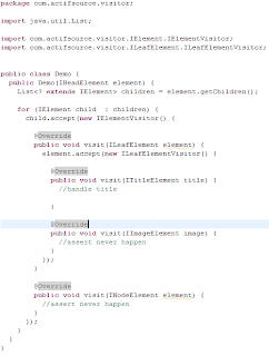
Later on, in your implementation code you can use the visitor to lookup the concrete type


As you can see there is no typecast needed, so you never get a ClassCastException. However if you look at the example, one major drawback of the visitor pattern is that if the hierarchy is not matching exactly, you have a bunch of empty methods. These methods can lead to confusion and doing nothing or throwing an exception isn't much better than a ClassCastException.

If you have the control over the source, you can easily introduce a new more specific type in your hierarchy to workaround this.


Now you can tag the child elements (in this case we have only one)


and the return type of the list can be changed to a more specific one


Using the new more specific visitor, there are no more unnecessary methods


Problem solved? Yes, if you have the freedom to modify each element for tagging it, when ever you create a child list. Otherwise you should look for a better solution.

Think a short time about, what you really want to do. You want to restrict the list to adding elements only of specific types and allow to query them later, while making sure that no type is forgotten when the code changes. Another possibility to add a visitor is to wrap the list element. To do so, remove the IHeadElementChild interface and the corresponding accept-method from the ITitelElement. Now add an implemention for the IHeadElementChild interface. Create factory method for each element allow in the childlist.


In the implementation of the IHeadElement always add the wrapper to the list, everything else can be left as it is. Now you are completely independent of the class hierarchy. Note that this solution will also work with classes provided by foreign frameworks.

If you already used actifsource to describe and generate your class hierarchy, you can leave the whole work to the generator and gain the advantage of more type-safety and less casts.

Monday, July 5, 2010

Modeling Software Architecture

In my last blog On the semantics of explicit dependency relations I explained the concept of explicit dependency relations between domain-specific components. The big advantage shows up when modeling on an architectural level.

A complex system is divided in layers/tiers and packages to manage code artifacts. This technical architecture provides an overview on the implementation.

On the other hand we find the business architecture where packages, areas, functionality, epics, etc. are used to structure domain objects.

On the semantics of projects and packages
Both the technical and the business architecture have one thing in common: they are structured not only with packages but also with projects. Modern IDE's as Eclipse, MS Visual Studio or InteliJ's Idea animate developers to separate different concerns in different projects.

All artifacts of a software system are structured using projects and packages.
But architecture lays above projects. Architecture describes how a system is divided into projects. This fact leads to the problem, that architecture can never be described by its projects alone.

It seems that describing architecture needs kind of an Über-Project which contains the overview how projects are interrelated. This overview shows packages and their dependencies as shown in my blog before.

There has to be an overview how projects are interrelated. This overview is the most important artifact to understand the technical architecture or business architecture.
The tricky thing: The overview provides an entry point whereat the details are managed in the projects. But nevertheless this architectural project should contain all the information to get a complete overview. This includes also detail information contained in the particular projects.

Let's assume that all green packages are modeled in the architecture overview while the red packages are realized as projects.


  • The architectural overview seems to define packages which contain other packages
  • At a certain level the architectural overview seems to reference packages from other projects to illustrate the dependencies

Packages as resources
In the current version of actifsource packages are reflected as file system folders. But it seems obvious that packages are much more then folders.

  • Package-structures have a project-specific meta model
  • Packages declare dependencies to other packages (according the meta model)
  • Package structures may be distributed over several projects (package references)
  • Packages can be mapped to file system folders
Packages are resources that contain other resources. Modeling packages as folders is just one way. Packages might also be modeled in the architectural overview without a folder representation. And package hierarchy structures are not limited to one project but distributed over many projects.

In one of my next articles I try to examine the technicalities.

Saturday, July 3, 2010

On the semantics of explicit dependency relations

Meta-modeling leads to components built along the own-relations (compositions) and to component-interdependencies along structural use-relations.

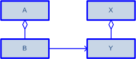
Component interdependencies might appear deeply nested in the component. Remember that component comes from the Latin word "componere" which means being composed. The following example shows a use-relation between A.B and X.Y.

Just looking at the components without knowing the internals we can say that there is an implicit dependency between the two components A and X.


If we could make this dependency relation explicit there would be a way to constrain the A.B-X.Y relations on higher level.


This possibility would allow you to control the component-interdependencies - even if they are nested deeply in the component structure.

Technical Architecture

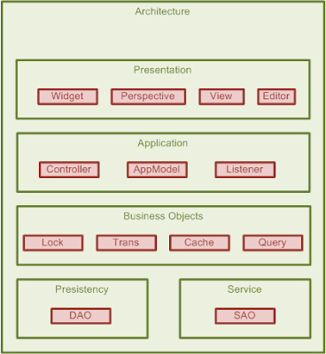
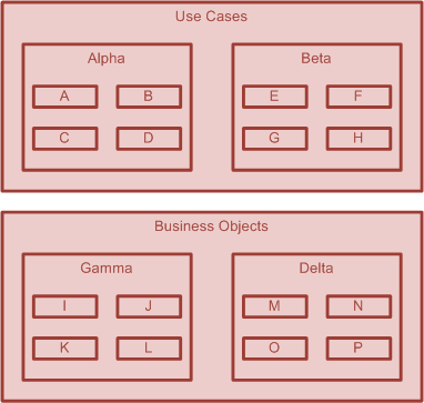
You may argue that component are not complex enough to control their use-relation by an explicit dependency. But imagine a software architecture which is based on layers and packages:

All packages and subpackages are somehow related to each other. Since the above diagram shows the technical architecture of our system the artifacts placed in the packages are templates (when generating) or simply code.

Just imagine you could explicitly define the dependencies between the packages. And now imagine that every template inter-dependency (one generic class using other generic classes) is checked immediately by the actifsource real-time validator.

Providing such a system your technical architecture would be documented soundly. And moreover actifsource would ensure that your code follows perfectly along the architecture.

Business Architecture

Another very interesting application of dependency relations is found when designing the business architecture. Coping with a complex business domain the relating business objects have to be structured to keep the overview.


Grouping domain-objects in packages and defining dependencies between the packages allows you to control use-relations between components from a higher level.

Providing such a system would allow you to group domain objects together for a perfect overview. Moreover actifsource would ensure that any relationship between components follows the well defined business architecture.
Conclusion

Modeling explicit dependencies allows you to control use-relations from a higher view. This view is what we usually call the architecture overview. actifsource could not only provide sound documentation of the architecture (technical and business) but also ensure at real-time that no artifact breaks the dependency rules.

The secret to this functionality lies in typed folders as Micha described in his blog Grouping Is Domain Specific Too. In one of my next blogs I try to workout the tricky details.

Friday, July 2, 2010

Writing C# using actifsource and eclipse

When people from the dotNet world hear about actifsource running on eclipse, they always ask us if it is possible to generate c# code for example. Today I want to show you how to create a c# application in eclipse using the emonic plugin.

First you have to install some prerequisites:

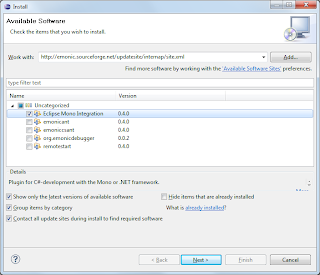
After you have installed them you need to setup emonic:


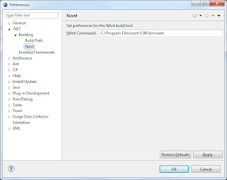
I only installed the "Eclipse Mono Integration", the debugger doesn't want to install at the moment and the other features are not required for this demo. When you have finished the installation, you first need to setup .NET preferences. Select the nant-binary-file:


and afterwards add a .NET-Framework Implementation. For example I used mono and chose the following settings:


Now create an actifsource projects for your meta model and the actifsource templates. I used the actifsource core model as meta model and wrote a simple data class template. The template is nothing special, but instead of writing java code, I wrote c# code:


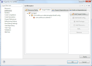
Note that I have created a separate actifsource project for the actifsource template and generation specific resources. With our multi model concept, there is no need to modify your meta model project, just create an extension project. Since the actifsource project containing the template is a Java Project and mixing Java Code with C# Code is not recommended, switch to .NET-Perspective and create a separate .NET-Project.


I used "Mono 2.0" as target, you may use another target framework. This setting is important, since generics for example are not available in "Mono 1.0".

For generating the data classes I first need some actifsource classes. I just reused one of my last examples and put it into a newly created asrc folder in the dotNet project.


Now there are only a few steps to do, add a project dependency to the template-project and define the target folder.


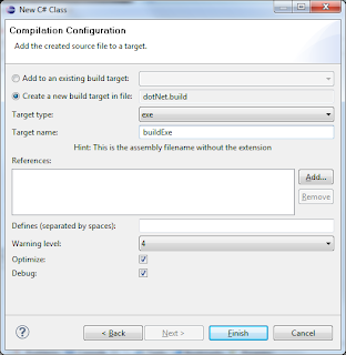
The c# files will be generated immediately after pressing "ok". In emonic to make them compile, you have to right click on them and add each file to the build.


When doing this the first time, you need to set a build target:


Finally I added a small demo application which creates two instances of the class "Person", fills them and queries the data for writing it to the console.


To run the application one needs to right-click on the exe-file and select run .NET-Application.


That's it. If you don't want to add each file, you need to edit the build script and make use of wildcards. One drawback using wildcards is that the emonic builder doesn't seem to detect file changes for these resources.

Structural vs. Functional use-Relations

In my last blog I talked about the semantics of permanent use-relations. In the meantime Micha had the idea not to differ between permanent and temporary relations but between structural and functional relations.

The idea remain the same. Some use-relations are important for the overall component structure and some are not. Let's have a look at some examples.

First of all, let's have a look at the following structure. Component owns Command owns Argument. But the Argument itself has a use-Relations to type. Imagine a function declaration f(int a, float b) where the argument a has a type int and b has type float. The relation of a method argument to its type is simply functional an will never appear as a relation in an UML diagram.


The second example show a meta-model which declares that components may extend/subclass other components. This relationship is clearly structural because it's important from the component's view. Just imagine the specialization relation in a UML diagram.


Quite special on the above relation is the fact that it's never necessary to name the role of the extends relation more specifically. Extends remains extends no matter what is extended.

The next example shows a meta-model for a component which has a collaboration relation to other components. The difference to the above design is that the collaboration relation has a role which has further information (i.e. at least a name.) For that reason the role has to be designed as an own class on the meta level called Collaborator in the subsequent example.


Let me give a résumé: First of all we distinguish structural and functional use-relation. As a rule of thumb only structural use-relations matters for the overall component structure.

Taking a closer look at structural use-relations one notice that there are relations with and without roles. If no role is needed the design is simple as seen above. If A extends B the extends relation between A and B needs no further information.


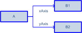
But if we do need to distinguish roles for a structural use-relation this role has to be modeled in a separate class providing at least a name. In the example below component A uses B1 as xAxis and B2 as yAxis. Note that xAxis and yAxis are instances of Collaborator.


It's quite interesting that the class Collaborator of the meta-model is visualized as a role in the instance-model. Since the decision if a structural use-relation needs a role or not is taken by the designer, we have to distinguish 3 different modes for use-relations:

  • functional use-relation
  • structural use-relation without a role
  • structural use-relation with a role
If we specify the use-relation mode on the use relation it becomes possible to visualize components and their interdependencies soundly.

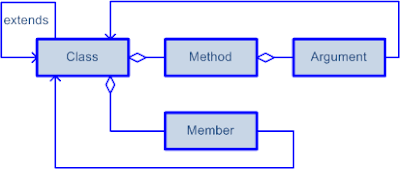
To conclude this blog let's think if this concept might work for a generic diagram editor which can visualize meta-model and model at the same time. For this reason let's have a look at the following simplified UML meta-model (which can be seen as meta-meta-model for our example).


  • The type-relation from Argument to Class is a functional use-relation
  • The extends relation from class to class is a structural use-relation without a role
  • The type-relation from Member to Class is a structural use-relation with a role (Member play the role)
At the moment it seems to me that our concept can be applied to all types of models. And this would be greatly simplify the development of the diagram editor.

Sunday, June 27, 2010

On the semantics of permanent use-relations

3 weeks ago I have written a blog with the Title Domain-Specific Presentation is Component Visualization. The idea was to provide a domain-specific component visualization which is aware of the different types of components and their relations.

Since then I've asked myself if there isn't any UML-way to visualize domain-specific components. I know how this sounds like: UML is generic by its very nature but not domain-specific. But let's give it a try anyway.

Before starting I have have to explain one thing first: actifsource distinguish only between two types of relations: the own-relation and the use-relation. The own-relation defines a strong coupling. If A owns B, B must not exist without A. The use-relation on the other hand doesn't imply any life-time semantics.

As I explained in my blog Software Architecture and Components, domain-specific components are defined implicitly around the own-relations of their meta-model.

Looking at the UML Component Diagram we find out that relations between components are realized as delegation connectors which connects a port to an element of the component.


And now the interesting question: does every use-relation between components lead to a port?

To answer this question, lets have a look at the meta-model of a UML class. A class can be seen as a component as well, composing

  • a name attribute
  • member variables
  • member functions
Lets have a closer look at member variables which can express to different relations:

  • own relation
  • use relation
Unfortunately, using 3rd GL's the semantic isn't always that clear. Programming in C++ I use pointers to imply use-relations and references or value-objects to imply own-relations whenever possible.

Before continuing the discussion, let's have a look at member functions. Functions consist of named and typed arguments. The types are modeled as a use-relation to other existing types.

So, what is the difference between the use-relation of member-variables to other types and the use-relation of typed arguments of a member function?

The use-relations of member-variables define the permanent relations between components while the use-relations of typed arguments of a function definition simply simply define a temporary relation.

Obviously we have to distinguish between two different of use-relations:

  • use-relations which define permanent relations between components
  • use-relations which define temporary relations between components
For a valuable component relation overview we are interested only in permanent relations between components which leads to the following definition:

Permanent use-relations shall be shown as ports in a component diagram.
In my next blog I try to explain how composite structures shall be visualized using the UML Composite Structure Diagram combined with the idea of ports for permanent use-relations.